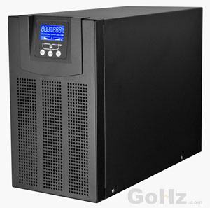
UPS Grounded Solutions There are various solutions currently employed to help mitigate potential problems of earthing and ground faults and impedance between the two separately-derived grounds—at the static-switch bypass and the double-ended substation. A transformer can be installed at the input of the static switch so that the neutral-to-ground bond established at the static switch will come from a separate source. This approach, however, can be costly, and the required transformer can be extremely large. Also, the transformer will contribute to inrush and additional impedance. But it may be of benefit in limiting maximum fault current available downstream from the UPS system. Another popular solution is to implement high-resistance grounding. HRG is not commonly used on a low-voltage system. The intent is to introduce a resistor to limit the current that flows at the neutral and ground bond, where the ground-fault current transformer monitors fault current (see figure 3). This method is difficult to implement, because it requires calculation of system capacitance and requires fine-tuning of the resistor in the field. It is also dangerous, requiring highly trained personnel to monitor the ground-fault alarm and then trace through the distribution system and isolate the source of the fault. Human error is already a major source of data center power loss. It does not seem a good idea to introduce yet more human intervention to trace and isolate fault current. In addition, the setting for the ground-fault sensors needs to be revisited any time a significant load is added that may change the system capacitance. It may seem that the solution is as simple as providing a zone-interlocking relay-protection scheme from the double-ended substation down to UPS static switch, and a distribution switchboard downstream of the UPS system. But ground-fault coordination is very difficult to design and install. Also, the static switch will transfer from the UPS module at a much faster speed than any fast-acting relay. It is essential to maintain operation of mission-critical facilities and data centers with a reliable distribution scheme. The design engineer should coordinate with the client to establish design parameters based on economics and level of required reliability for mission-critical facilities and ensure that the final product is a facility that meets all of the client's long-term operational requirement.
Chat with us on WhatsApp
×
This is your website preview.
Currently it only shows your basic business info. Start adding relevant business details such as description, images and products or services to gain your customers attention by using Boost 360 android app / iOS App / web portal.

2018-08-10T10:34:05
UPS Grounded Solutions There are various solutions currently employed to help mitigate potential problems of earthing and ground faults and impedance between the two separately-derived grounds—at the static-switch bypass and the double-ended substation. A transformer can be installed at the input of the static switch so that the neutral-to-ground bond established at the static switch will come from a separate source. This approach, however, can be costly, and the required transformer can be extremely large. Also, the transformer will contribute to inrush and additional impedance. But it may be of benefit in limiting maximum fault current available downstream from the UPS system. Another popular solution is to implement high-resistance grounding. HRG is not commonly used on a low-voltage system. The intent is to introduce a resistor to limit the current that flows at the neutral and ground bond, where the ground-fault current transformer monitors fault current (see figure 3). This method is difficult to implement, because it requires calculation of system capacitance and requires fine-tuning of the resistor in the field. It is also dangerous, requiring highly trained personnel to monitor the ground-fault alarm and then trace through the distribution system and isolate the source of the fault. Human error is already a major source of data center power loss. It does not seem a good idea to introduce yet more human intervention to trace and isolate fault current. In addition, the setting for the ground-fault sensors needs to be revisited any time a significant load is added that may change the system capacitance. It may seem that the solution is as simple as providing a zone-interlocking relay-protection scheme from the double-ended substation down to UPS static switch, and a distribution switchboard downstream of the UPS system. But ground-fault coordination is very difficult to design and install. Also, the static switch will transfer from the UPS module at a much faster speed than any fast-acting relay. It is essential to maintain operation of mission-critical facilities and data centers with a reliable distribution scheme. The design engineer should coordinate with the client to establish design parameters based on economics and level of required reliability for mission-critical facilities and ensure that the final product is a facility that meets all of the client's long-term operational requirement.
2018-08-10T10:34:05
Keywords
- UPS system
- ground faults
- UPS static switch
- design parameters
- system capacitance
- distribution system
- additional impedance
- isolate fault current
- data center power loss
- operational requirement
- reliable distribution scheme
- distribution switchboard downstream
- current transformer monitors fault current
- maximum fault current available downstream

Submit Your Enquiry